Volkswagen never bothered to add even an idiot light to the Beetle to warn of overheating. That's quite an oversight for an air cooled engine that is prone to self-destruction from running too hot. Head temperatures are reported to range up to 315C while oil temperature can reach 120C. Some aftermarket temperature sensors and overheat warning systems have become available over the years. These include the Berg dipstick sensor, which turns the oil pressure warning light on if the oil temperature exceeds a setpoint. Similarly a sensor from Bugpack attached to a shroud screw and turned on the oil pressure light if the temperature of the shroud exceeded 100C. Neither of these approaches gives an actual temperature reading, and both interfere with the function of the oil pressure warning light.
Recently I came across an excellent online article by " skyoga " in which a digital kitchen thermometer was used to make a very inexpensive head temperature sensor! This article inspired me to try my own experiments with kitchen thermometer gauges.
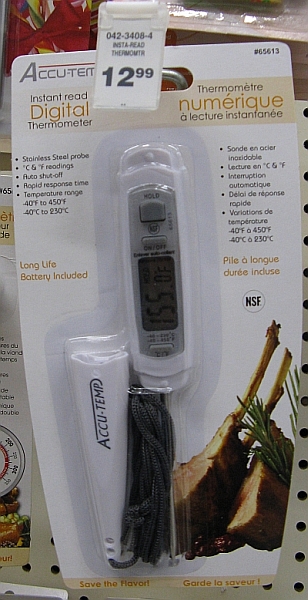
At local stores I found two basic types of digital kitchen thermometers. Type A had a simple display integrated with the probe in a single unit. The packaging advertised an operating range from -40 to 250C. This thermometer retailed for about US$13. The one I bought had the brand name Accutemp but looks identical to the Trutemp device used by "skyoga". I would guess that the thermometers all come from the same Chinese electronics suppliers and are sold around the world under various names.
|
|
|
|
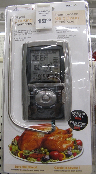
The Type B thermometer had a detachable probe on a long cable, and a much more complicated display including a timer. It retailed from about US$14 to US$20 depending on the store. The packaging didn't specify a temperature range but after buying one I found it would only read to 100C. Clearly the Type B thermometer doesn't have the range to be useful for a head temperature sensor, but it might be suitable for an oil temperature sensor.
 |
|
|
Both types of thermometer use a thermistor (temperature sensitive resistor) as the primary temperature sensor. Surprisingly the thermistors were quite different in value. The Type B thermistor had a value of 14 kohm at room temperature, dropping to 1.2 kohm at 95C. The Type A thermistor had a much higher resistance at a given temperature.
 |
|
|
|
|
 |
|
|
I cut the cable and spliced in standard household 4-conductor twisted pair telephone wire to allow the sensor to connect to the readout unit mounted on the dash. I threaded the telephone wire over the left rear fender, following the path of the original wiring harness, and then routed the cable under the floor mats and carpet to the dash. I soldered the spliced connections and sealed them with heatshrink for electrical insulation and mechanical strength. The readout unit had a magnetic back which allowed easy attachment to the glove compartment door.
Since oil temperatures can be somewhat higher than 100C, one could add a 100 ohm resistor in series with the thermistor to extend the high end of the range by about 5C. Of course it would then be necessary to mentally add this 5C offset to the reading on the display to get the actual oil temperature. The accuracy of the low end of the temperature scale would be compromised since the resistance-temperature characteristic is very non-linear. I haven't bothered to make this modification- I just use the 100C mark as a warning that the engine is getting very hot, and try and adjust my driving to keep the oil under 100C.
I had expected to have problems with electromagnetic interference from the ignition, and was planning to connect the two unused wires in the telephone cable to chassis ground to provide shielding and minimize the interference. However, I found this wasn't necessary.
 |
|
|
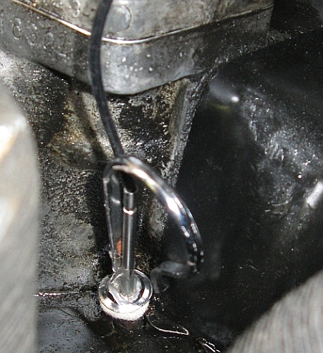
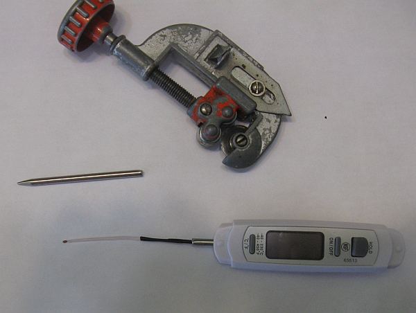
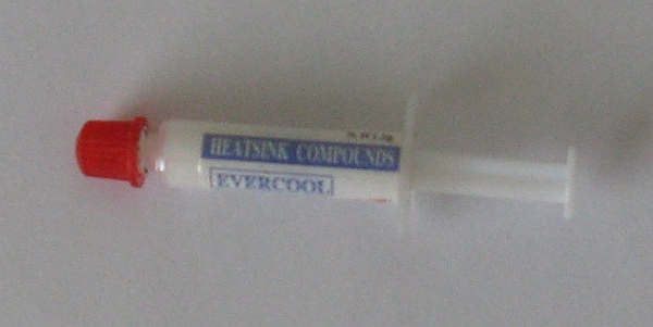
I then cut the leads to the thermistor and spliced in another length of telephone cable threaded from the engine compartment to the dash as described above. Once again I soldered the connections and then covered them with heatshrink. I cut a 20 cm length of old steel fuel tube and jammed this through the rubber rear engine seal to provide a feedthrough for the sensor wires to reach the head. The tube also helped protect the wires from hot exhaust pipes. I bent the fuel tube to bring the wires close to the cooling fins on the head. After pushing the thermistor through the pipe I threaded it to the tip of an alligator clip just as described in "skyoga". To try and get the best possible thermal contact between the head and the thermistor I filled the tip of the alligator clip with the thermal compound applied between the CPU and cooling fan in computers (available from any computer store).
 |
|
|
I then clipped the thermistor to a cooling fin on cylinder 4, choosing a location away from the path of the cooling air.
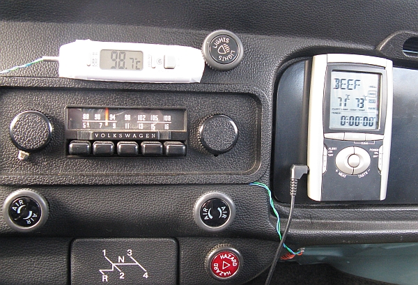
The photo below shows the dash with both oil temperature and head temperature readouts.
 |
|
|
So far I haven't had problems with electromagnetic interference with the head temperature sensor, even without grounding the unused wires in the telephone cable.
It's worth noting that, contrary to urban legend, on 1971 and later engines with the doghouse oil cooler, Cylinder 3 should receive the same amount of cooling air as the other cylinders and should not run appreciably hotter, so Cylinder 4 should be as good a place as any to attach the thermistor.
The head sensor responds much more quickly to changes in engine load than does the oil temperature sensor, as one would expect. At 100 km/hour with 30C ambient the head sensor reads between 145 and 150C, depending on the slope of the road. The highest value I've seen so far is 153C, recorded when the engine returned to idle immediately after a long highway run. This demonstrates the importance of keeping the revs up a bit to help the engine cool down when leaving the highway.
I think the oil temperature sensor is providing a fairly accurate reading of the temperature of the oil in the sump. Exactly what the head temperature sensor is measuring is open to question. Of course the thermal contact between the thermistor and the head isn't perfect, and for that matter different parts of the head will run at different temperatures. 1975 and later fuel-injected Type 1 engines use a special thermistor sensor (BOS-0-280-130-012) that screws into the head, and this sensor will almost certainly read higher than a thermistor clipped to a cooling fin. The clip-on sensor is most useful in building a history of head temperature values. Any sudden increase in head temperature under a given load is a cause for concern. This particularly true for changes made to timing or fuel mixture, or any other engine modifications. For example, I'm planning to add a Mexibug filter pump (part VWC-043-115-115 ) to my car soon. The filter pump places the filter canister directly in the path of the cooling air leaving Cylinder 4. I'm concerned this will decrease the efficiency of the cooling system and raise head temperature. If this proves to be the case, I'll be switching back to the original unfiltered Type 1 system.
Garry Tarr Jan. 18, 2013