Maury ATS - Load Pull Guide
Document History
- Revised 2005-2-17: John Danson
- Revised 2004-12-7: John Danson (aka: Dr. Danson) & Harpreet Panesar (aka: HP)
- Created 2004-7-6: Steve Knox & Peter Chyurlia
Document Outline
Introduction
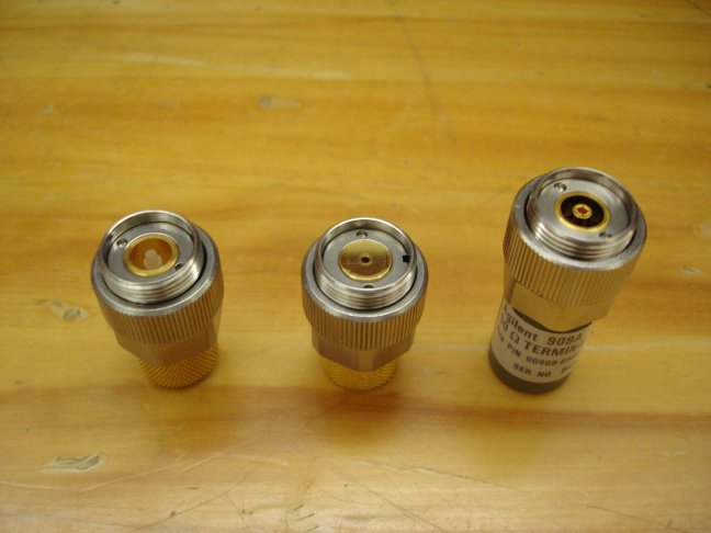
Connector Overview
- There are several types of connectors used in the load pull setup:
- SMA
- 3.5mm
- K (2.92mm)
- 7mm (APC-7)
- N
- BNC
- Incorrectly mating these connectors can cause PERMANENT DAMAGE.
- Please familiarize yourself with the connectors.
Calibration Overview
- The load pull system relies on accurate s-parameter measurements of all the blocks in the system.
- To obtain accurate measurements, the VNA must be calibrated.
- Calibration removes the effects of cables, connectors and probes from the measurements.
- Once the VNA is calibrated it is important to move the cables as little as possible.
- For information on s-parameters, see the following papers:
- For information on VNAs, see the following papers:
- There are two main VNA calibrations required for the setup at Carleton:
- On-wafer calibration: uses a calibration substrate (SOLT) to remove all effects (cables, adapters, tuners, probes, etc.) up to the probe tips.
- 7mm calibration: uses 3.5mm to 7mm adapters on the VNA cables. Calibration standards are SOLT from the Maury 7mm cal. kit.
- Maury highly recommends TRL calibration, however the 8720ES VNA does not support this type of calibration without option 400. See: Maury ATS Manual: Accuracy Considerations for S-parameter Calibration.
- For information on calibration, see the following papers:
Load Pull Overview
- The top link below has the best introduction to load pull, but a brief explanation is presented here.
- In the Carleton installation, the load pull uses sliding mechanical tuners (actuated by stepper motors) to synthesize different load or source impedances to the DUT.
- By applying a tone at the input to the load pull system and measuring the power at the output while varying the load impedance, the point of maximum output power can be determined. A similar technique applies at the input by measuring the reflected power to determine the best input match.
- Software controls the instruments and the tuners. When measured s-parameters of the different blocks in the system are entered into the program, the software can determine the large signal characteristics of the DUT by subtracting the effects of couplers, bias networks, tuners, etc.
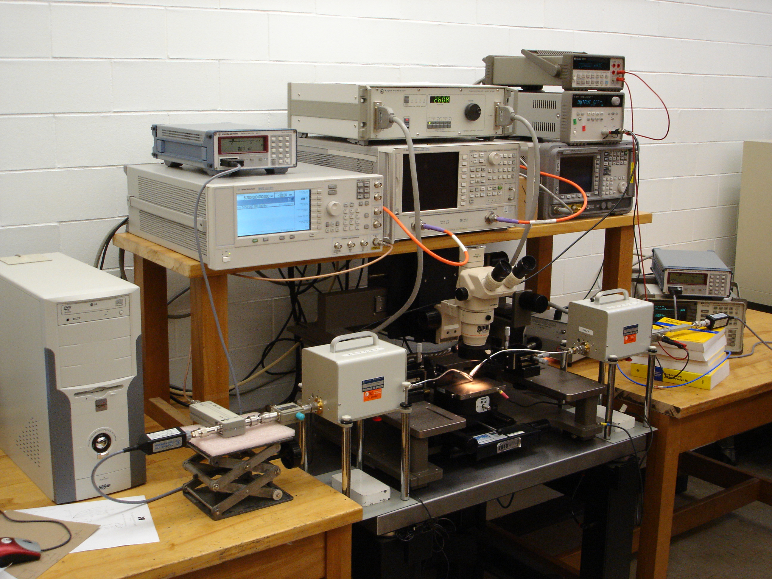
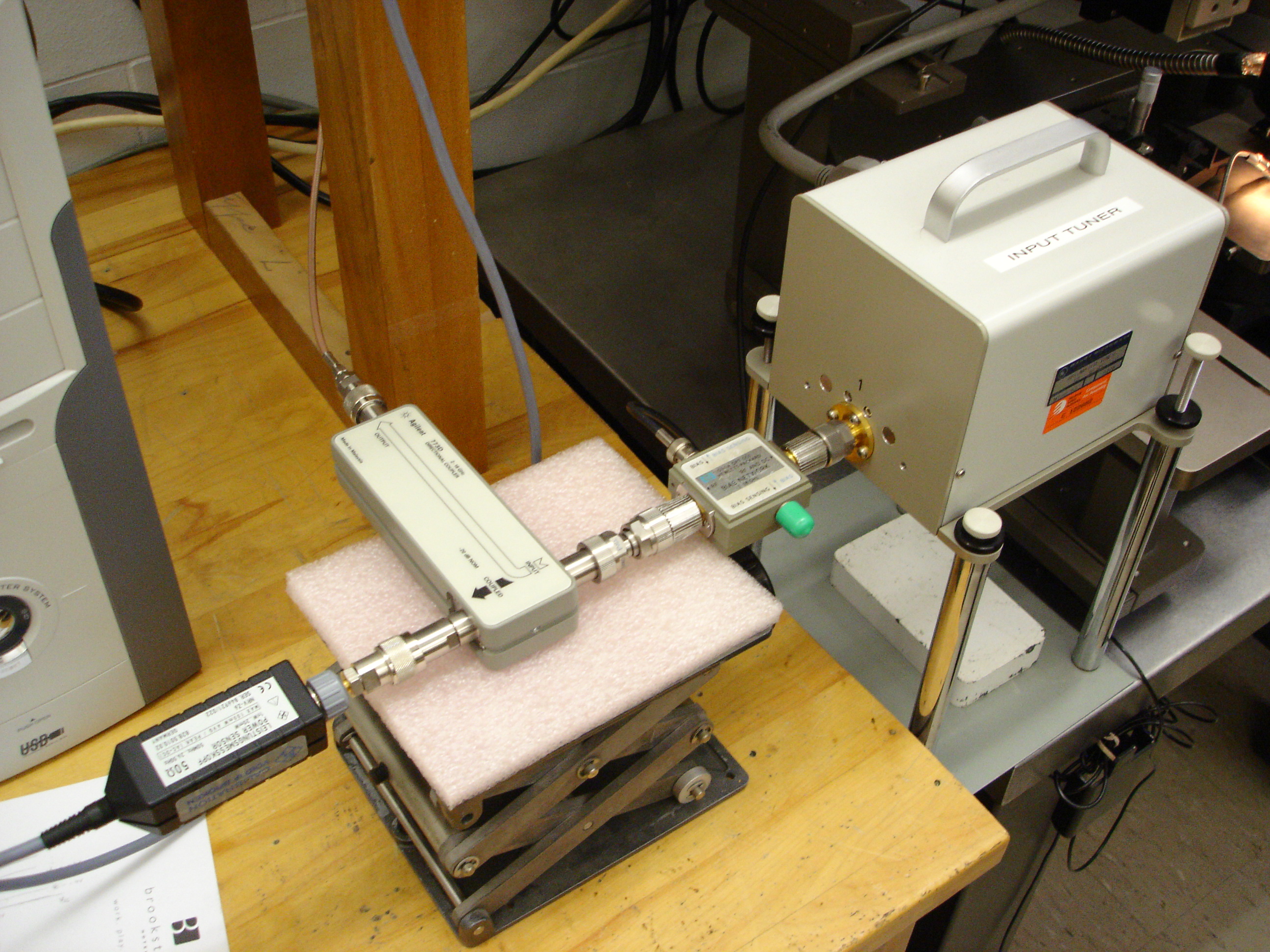
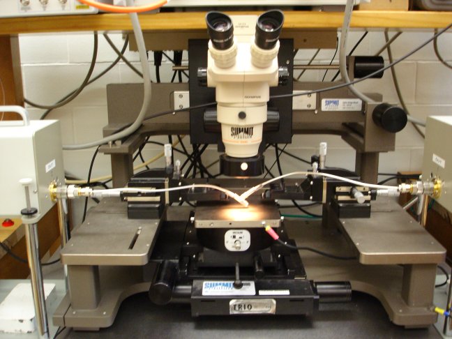
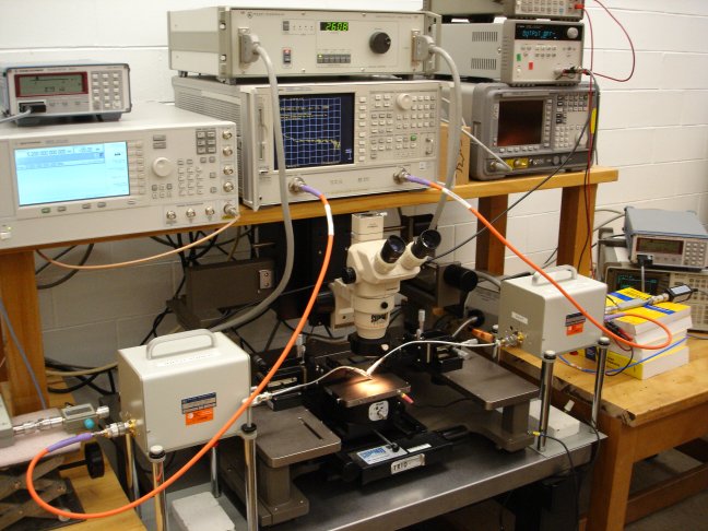
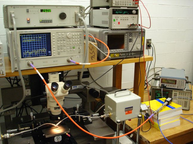
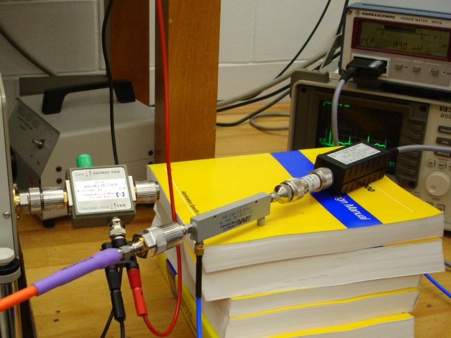
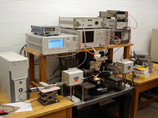
- The three images below show the main components and connections in the load pull.
The load pull system set up for power load pull measurements (click for larger image).

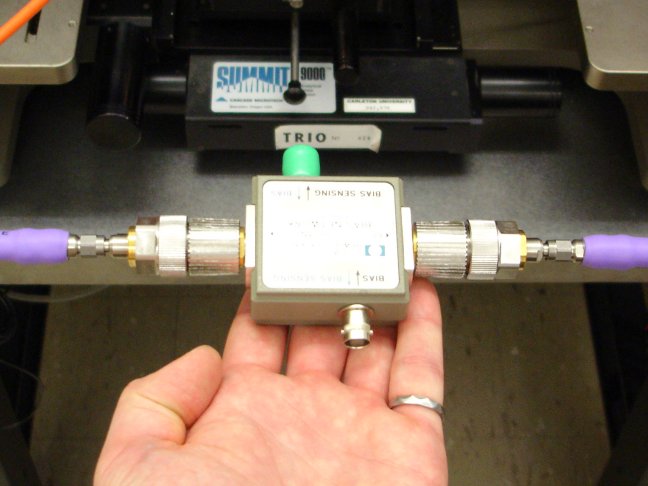
The input bias T, power sensor and coupler (click for larger image).
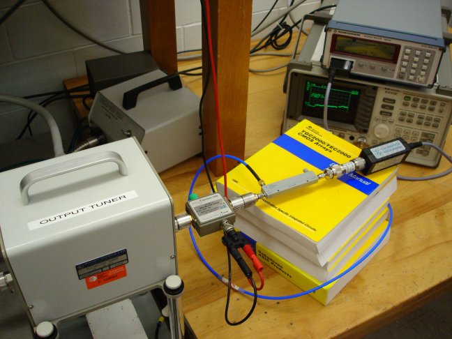
The output bias T, coupler and power sensor (click for larger image).
- For information on load pull and fixture characterization, see the following papers:
Legend
- Agilent 8720ES VNA
- Front-Panel Key: Represents a key physically located on the instrument
- SOFTKEY: Represents a softkey, whose label is displayed on-screen
- ATS300 SNPW software
- SNPW Button: Represents a button in the SNPW software
- SNPW Menu: Represents a menu option in the SNPW software
Load Pull Setup
Calibrating VNA and Probes
Determining the s-parameters of the THRU
- This step is needed for the full system calibration
- For additional information see: Maury ATS Manual: S-Parameter Calibration and Maury ATS Manual: 2-Port Measurements
- Tell SNPW that the VNA is calibrated: Calibrate, 2 Port S-Parameters..., VNA Cal is Ready.
- To measure the s-parameters of the THRU standard on the calibration substrate go to: Measure, S-Parameters, 2-Port.
- Make sure the bias is turned off for this step. Under "DC Bias" click Details. For "Bias Mode, Specify" select "None" then click OK.
- Click Measure.
- Enter a label and filename to save the s-parameters.
Calibrating the Output Bias Network
Calibrating the Output Power Meter
System Thru Calibration
- The tuners were initially calibrated for 4 frequencies (2.4GHz, 3.15GHz, 5.2GHz and 14GHz - see below). The s2p file for the THRU requires the s-parameters for these frequency points in order to complete the System Thru Calibration (even if you are only doing load pull measurements at one frequency).
- One way to do this is to trick the system by ensuring that "dummy" s-parameters for the missing frequencies are present (i.e. if you're measuring at 2.4GHz, then you need the s-parameters for the other frequency points as well). Copy and paste the missing data from
CS5150 - 90deg thru.s2p
- A better solution is to calibrate the system at all 4 frequencies from the very beginning.
- If you are testing your circuit at a frequency not listed above, then the tuners must be calibrated for that frequency as well (this is roughly an 8 hour process).
- Calibrate the system
- For additional information see: Maury ATS Manual: Power Calibration
- Ensure all parts of the load pull system are connected together (probes, tuners, bias networks, couplers, power meters, etc.)
- Lower the probes on the THRU standard on the calibration substrate.
- Go to SNPW: Calibrate, Power, New Cal....
- Change the s-parameter file for the thru to the one measured earlier.
- Set desired power range and frequencies.
- Click OK.
- It is important to wait for the system to finish polling the instruments over the GPIB interface before moving to the next step. The instruments should stabilize about 10 - 20 seconds after clicking Next.
- Click OK when prompted to connect the thru.
- SNPW will ask you to connect the power meters to the reference but since there is no reference, zeroing both power meters will suffice (make sure you have local control) and click Skip.
- SNPW will ask if you want to re-initialize the tuners. Click Yes.
- SNPW should start the calibration.
- A Smith Chart with points on it should appear.
- All points should be inside the Smith Chart.
- If the points are outside the Smith Chart, SNPW has mathematically determined (by cascading the s-parameters of the blocks) that there is too much power in the system (i.e.: power is being generated by the THRU - obviously this is not possible).
- If this is the case it is possible that the s-parameters of the blocks in the system have not been measured properly, or that the output power meter is measuring more power than is physically possible.
- If the calibration is successful enter a label and filename to save the power calibration data.
- Check the calibration
- For additional information see: Maury Microwave: Basic Verification of Power Load Pull Systems and Maury ATS Manual: Gt(s) and Delta_Gt
- Leave the probes on the THRU standard.
- In SNPW: Measure, Power.
- Select a frequency, set the bias to "none".
- Ensure the "Use S-Parameters" box is checked.
- Click OK to bring up the Power Measurement view.
- Select 5 - 6 points around the outside of the Smith Chart (Load or Source as desired).
- Ensure Gt, Gt(s) and Delta_Gt are selected as parameters to be measured: Setup, Select Parameters.... Double-click to select the parameters on the table and click OK to close the table.
- Gt is the measured transducer gain.
- Gt(s) is the transducer gain calculated from the s-parameters.
- Delta_Gt is the difference between the two and an indication of how well the system is calibrated.
- Click LP or SP (depends whether Load or Source points were selected above) to do the measurement.
- To display the parameters versus phase, go to: View, Plot vs Phase.
- When the swept phase display appears, select Gt, Gt(s) and Delta_Gt as the displayed parameters: View, Parameters.
- The plot can be re-scaled by clicking on the range numbers in the legend to the left of the plot.
- Gt and Gt(s) should have some loss.
- Delta_Gt should have a peak-to-peak ripple of 0.2dB. If the ripple exceeds 0.5dB peak-to-peak, the system should be recalibrated.
Load Pull Measurements
DC-IV Curves
- SNPW can measure DC-IV curves by sweeping the DC supplies that bias the circuit.
- For additional information see: Maury ATS Manual: DC I-V Curve Measurement
- Lower the probes onto the DUT. Turn the microscope light OFF, depending on the device sensitivity to light.
- Go to Measure, DC-IV. If the message "Invalid bias mode (0)" appears, this is because Bias is set to "None". Click on the Bias System block to change the bias mode.
- Set bias limits and sweeps.
- Click OK to measure.
- Enter a label and filename to save the curves.
- A Matlab file has been created to parse the data. Some sample data is provided (place the M-file and the data in the same directory):
S-Parameters
- For additional information see: Maury ATS Manual: S-Parameter Calibration and Maury ATS Manual: 2-Port Measurements
- As an aside: To save the s-parameters on the VNA to a floppy disk in Touchstone format (*.s2p):
- The VNA must have been calibrated in Full 2-Port mode, otherwise it will need to be re-calibrated.
- Press Save/Recall, Select Disk, Internal Disk.
- Press Save/Recall, Define Disk-Save.
- Make sure the following options are set: Data Array ON, Raw Array OFF, Format Array OFF, Graphics OFF, Data Only ON, Save Using ASCII.
- Press Return, Save State. A message saying that the data is being saved in Touchstone format should appear.
- Calibrate the VNA
- Connect the VNA cables to the input and output bias networks.
- In SNPW: Calibrate, 2 Port S-Parameters. Set the frequencies, etc. as required.
- Calibrate the VNA.
- Click VNA Cal is ready.
- Fixed Bias S-Parameters
- Measure the s-parameters: Measure, S-parameters, 2-Port.
- Set the bias as required on the form.
- Click Measure.
- Enter a label and filename to save the s-parameters.
- Swept Bias S-Parameters
- include matlab files and source data
- mention about 0V bias setting
- Measure the s-parameters: Measure, S-parameters, 2-Port vs Bias.
- Set the bias as required on the form. If additional bias settings need to be adjusted, click Details.
- Click Measure.
- Enter a label and filename to save the s-parameters.
- Some important information about Swept Bias S-Parameter measurements:
- Setting any of the fixed bias conditions to 0V seems to prevent the DC supplies from being switched on during the measurement. If 0V bias is required, disconnect the network from the supply and short the DC input on the bias network to ground. Then enter a "dummy" value for the SNPW software.
- A Matlab file has been created to parse the data into a 3D matrix for manipulation. Some sample data is provided (place the M-file and the data in the same directory):
Load and Source Pull Power Measurement
- For additional information see: Maury ATS Manual: Power Measurements
- Go to: Measure, Power.
- Set the frequencies and bias points as required.
- Select 5 - 7 points around the Source Smith Chart and 4 - 5 in the center, then click SP to do a source pull.
- Enter a label and filename to save the source pull data.
- Now look at the optimum impedance and select a few more points around it and repeat the pull to refine the data. Use incremental mode so it won't re-scan the original points.
- Enter a label and filename to save the source pull data.
- Once you are satisfied with the source impedance, repeat the same method for the load pull.
- One or two iterations between source and load pulls may be necessary to determine the optimal impedances.
- NOTE: for load pull and source pull, impedances near the edge of the Smith Chart are not to be considered accurate, so move them over from the edge manually and then redo the opposite pull (i.e. if you move the load impedance, do a source pull)
- A 3D visualization package (Surfer 8) is part of the load pull system and partially integrated with the ATS software.
- This is an advanced graphics package for viewing load pull contours, etc.
- The installation CD seems to have been lost, so the software and serial number are provided here:
- For additional information see: Maury ATS Manual: Enhanced Graphics
Miscellaneous
This information has to do with setup, debugging and Carleton-specific details of the system - things that don't clearly fit anywhere else.
Maury ATS Info
Tuners
- The tuners are somewhat sensitive devices and should not be subject to mechanical shocks. To prevent damage to the carriage, the red screw located underneath the tuner should be installed as per the instructions in the manual when the tuners are moved. This screw fixes the position of the carriage and relieves stress on the stepper motors and internal components.
- Characterizing the tuners
- The tuners were initially characterized for 4 frequencies (2.4GHz, 3.15GHz, 5.2GHz and 14GHz).
- For measurements at other frequencies, the tuners will need to be calibrated at these frequencies.
- The main source of confusion with characterization lies in the numerical labels on the tuners. One side is labelled "1" and the other "2". This gives the false impression that the tuner should be connected to these ports on the VNA during characterization. During characterization the tuner should be connected such that the side that will be connected to the DUT during load pulls is connected to port 1 of the VNA. The tuners have one side labelled "DUT" to make this clearer. This means that the input tuner will need to be turned around (so that the control cable is facing outwards) during characterization.
- Although the ATS manual indicates that bias T's and other passive components can be combined with the tuners and characterized as a unit, the changing nature of equipment setups at Carleton makes this impractical. The tuners should usually be characterized alone.
- For additional information see: Maury ATS Manual: Calibrating the Tuners
Instrument Drivers / GPIB Interface
- GPIB Interface
- Communication between the software and the instruments occurs over the GPIB bus. Instruments are assigned addresses and these addresses are entered into the SNPW software. Most commands are ASCII text strings that are sent to the instruments to set or query the instrument state.
- Maury recommends the National Instruments GPIB PCI card for use in the PC to meet the tight timing requirements of the software.
- There are several useful tools in the NI-488.2 software package for testing and debugging software that uses the GPIB bus:
- Measurement and Automation Explorer provides a list of all the instruments connected to the GPIB bus as well as their addresses.
- NI Spy captures all communication on the GPIB bus. When communication between drivers and the instruments does not appear to be working, this is an excellent starting point for debugging the problem.
- SNPW requires that the default settings for the GPIB interface be changed (see: Maury ATS Manual: Modify the National Instruments Default Settings). The location of the settings panel is different than described in the Maury ATS Manual. The correct location is described here.
- Instrument Drivers
- SNPW supports many instruments, however the occasional driver needs to be written. This allows any instrument that can be controlled by GPIB commands to be used in the setup.
- A good overview of the procedure can be found here: Maury ATS Manual: Programming Custom Instrument Drivers and User Functions
- The best way to start programming a driver is to take the source code for an existing instrument that is in the same family or uses similar commands, then modify it to work with the new instrument.
- Microsoft Visual C++ Studio v6.0 has been installed and projects are available with the default settings required to compile the drivers (separate projects for bias drivers (compiled as DLLs) and other drivers).
- Due to the way SNPW installs itself (basically overwrites all of its files in the program directory) Carleton drivers have been placed in a separate directory. New drivers should be placed in this directory. This prevents any drivers that might have the same name as existing drivers from being overwritten.
Calibration
- Most of the information on calibration has been provided above, however this last part has to do with managing cal kits as well as entering calibration coefficients for new cal kits.
- VNA Cal Kit Manager is a program that can store calibration coefficients as well as load those coefficients onto the VNA over GPIB. The program is freeware and available here: VNA_Cal_Kit_Manager_setup.exe
- The 7mm SOLT calibration coefficients are loaded onto the VNA with this software. The calibration file is located here: MM2660B.ckm
- An excellent explanation of entering calibration coefficients for other cal kits can be found here: Agilent: Specifying Calibration Standards for the 8510 VNA